Spin Launch
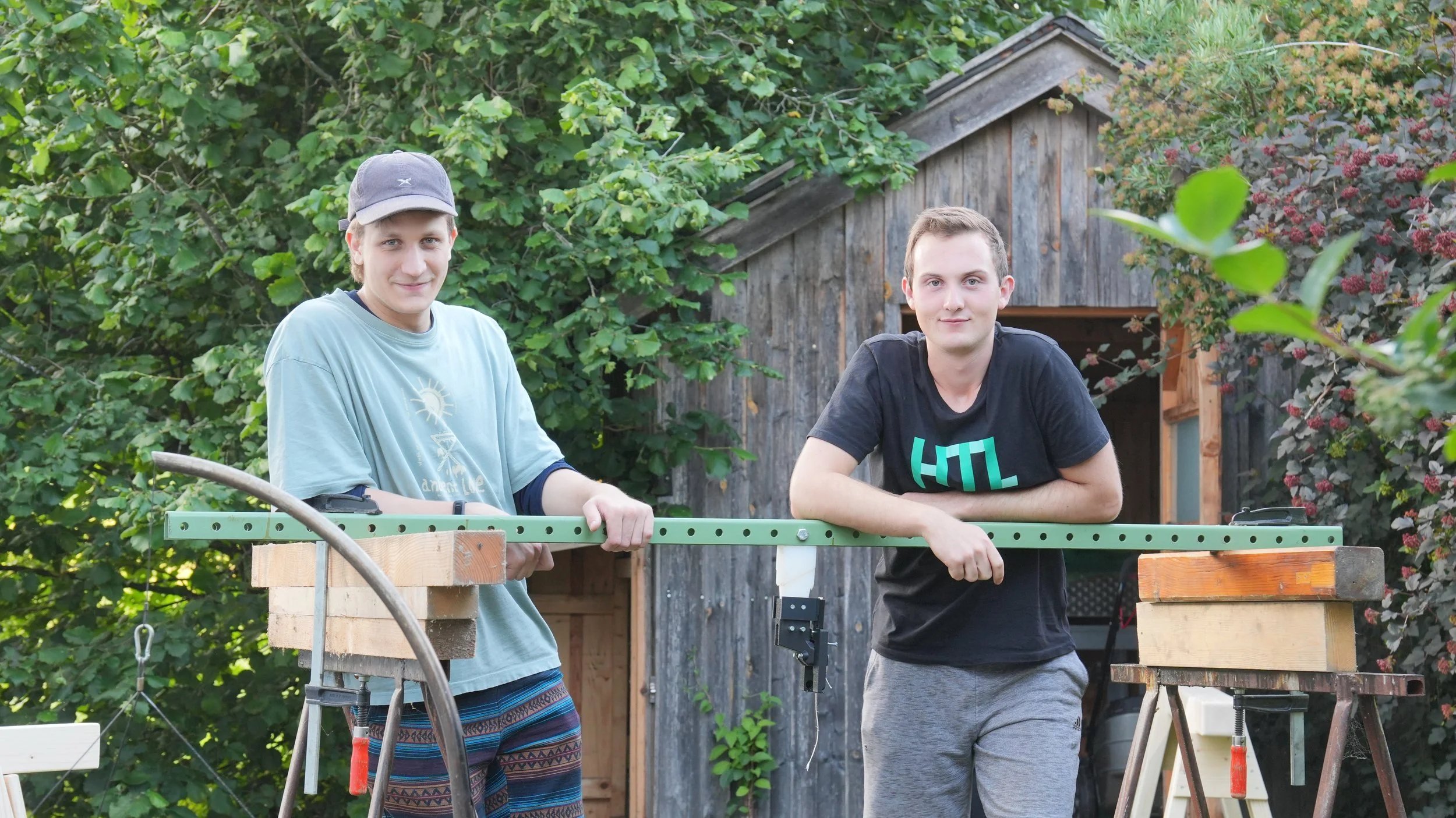
Spin Launcher Hero Image
The idea of flinging rockets into space sounds simple, but the engineering quickly becomes complex. We wanted to see how far we could push this concept using accessible materials and a low budget. This project pushed us to solve problems in timing, structural design, and payload handling. In the following, we share details about the build, simulations, and lessons learned from testing.
The Idea of Launching by Rotation
If you have been following the space industry, you have likely come across the controversial videos of SpinLaunch, a company attempting to hurl payloads into orbit using a giant rotating arm. The concept is simple in theory: spin the payload up to launch velocity and utilize this kinetic energy for the most energy-intensive phase, reaching the upper layers of the atmosphere, where a small rocket engine takes over and provides the final boost to orbit.
The catch is the insane G-forces during spin-up due to centrifugal acceleration. In its full-scale version, SpinLaunch was preparing for over 10,000 g – enough to make a smartphone weigh as much as a car. At those accelerations, components on a PCB start detaching. That’s why SpinLaunch spent most of its development efforts on ruggedizing the structure and electronics of both the rocket engine and the payloads.
While the idea of launching by rotation might be very limited on Earth, it could prove valuable elsewhere in the future. On celestial bodies with thinner atmospheres and lower escape velocities - the Moon, for instance - a rotational launch system might be an efficient alternative to classical rockets.
The Project at a Glance / Getting Started
Our goal was not to reach the heights of our big role model but to build a cheap and reliable alternative to the solid rocket motors we have been using so far for our launches.
Derived from this goal, we set out the following cornerstones for our build:
Launch Height: 120m
Payload Mass: 1.5kg
Variable Launch Angle
Budget: 2000€
Knowing these boundary conditions, we ran the first calculations and simulations to get a sense of the forces at play. After a round of optimization and some pragmatic trade-offs, we settled on a 4-meter arm diameter and a rotation speed of 400 RPM. At that point, it became clear: this wasn’t going to be a quick and easy project. We would need a sturdy support structure and a significant amount of power to run this thing. But as we would soon discover, the real challenges lie in the more subtle details.
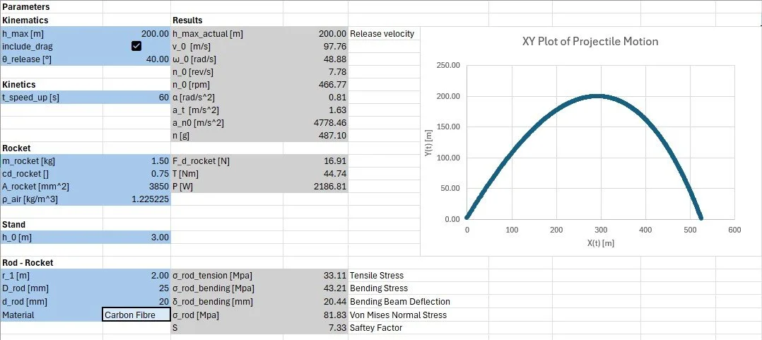
Excel Trajectory Calculations
Where It Gets Tricky
Catching the Perfect Moment: Optimizing the Release
The hardest part of Spinlaunch isn’t spinning up the payload, but letting it go in exactly the right way - a detail that determines the rocket’s stability, trajectory, and overall launch efficiency.
For an ideal launch, three conditions must be satisfied simultaneously:
No residual spin - the payload’s net angular velocity at release should be zero.
No sideslip - at release, the rocket’s axis must align with its velocity vector.
Spin-up efficiency - during spin-up, the payload’s orientation should deviate minimally from its most efficient, streamlined orientation.
Our solution for this is what we call differential release: the payload is mounted at two points, which open at slightly different times. Once the first latch opens, the rocket may pivot around the second like a pendulum under the centrifugal forces. If you get all parameters right and the second point releases at just the right moment, it is possible to meet all three conditions above.
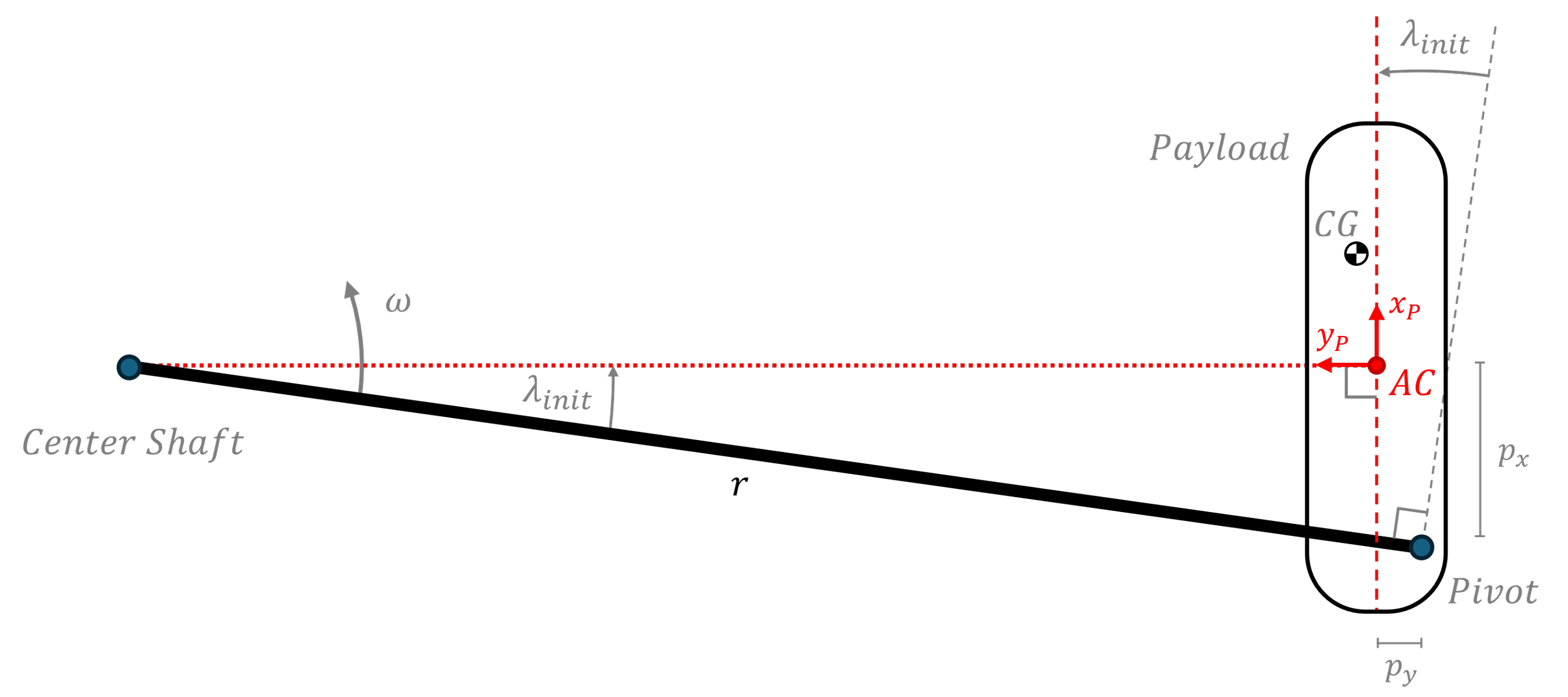
Model of the system in the rotational frame of reference
To understand and refine this motion, we built a dynamic simulation of the pivot phase – the part of the release phase where only the second latch is attached. We modeled the rocket as a rigid pendulum in a rotating frame fixed to the spinning arm, driven by centrifugal acceleration. Aerodynamics turned out to play a secondary role during this short pivot phase, so we neglected any such effects.
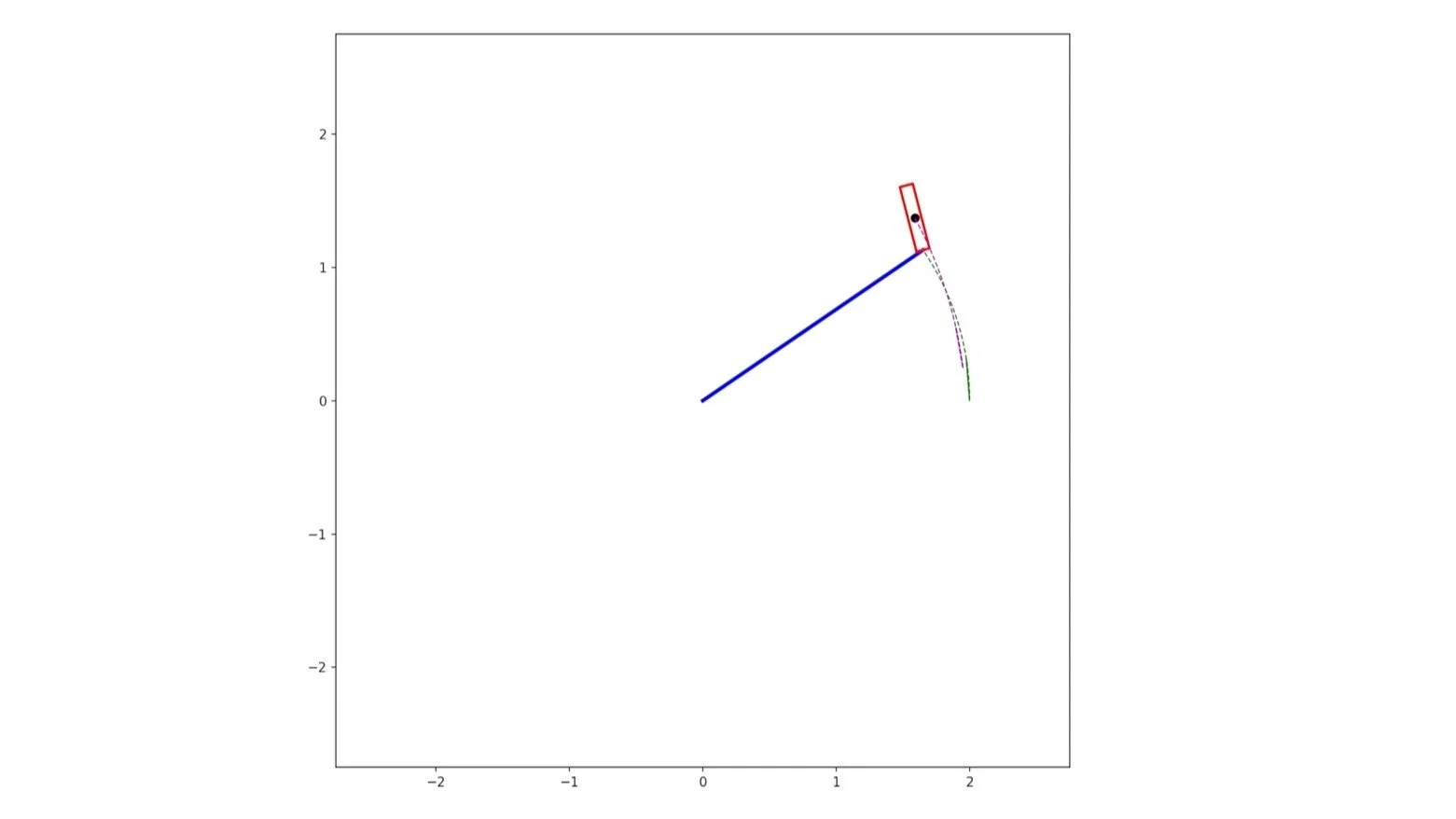
Simulation of Rocket Behavior after Front Clamp Release
With the model in place and three constraints to satisfy, we first had to decide on a corresponding set of release parameters. Without delving into the technical details, these parameters can be reduced step by step using our boundary conditions until only a single degree of freedom remains. The final condition, zero residual spin, was achieved by tuning this single variable through a binary search. (We are working on a documentation for more details on the parameter choice, optimization, and simulation.)
Finally, we had a way to determine the optimal release parameters for any payload imaginable. Interestingly, time never entered the equations: the optimal release parameters do not depend on launch velocity. This was great news because it meant the mechanism was inherently robust – it could be built based purely on geometry instead of relying on timing precision.
With the theory proven, the challenge shifted towards designing the actual release mechanism.
Designing a Reliable Release Mechanism
The requirements were clear: we needed a mechanism that could withstand the enormous G-forces during spin-up while still being able to disengage within a few milliseconds. It had to work with any payload and with exceptional repeatability.
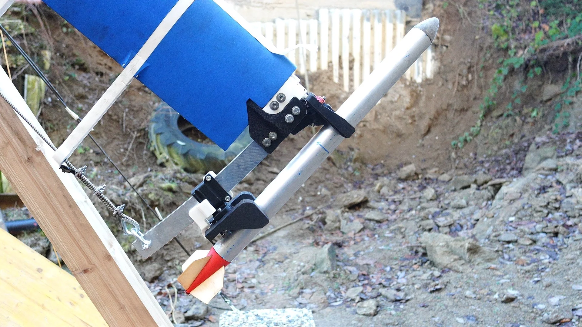
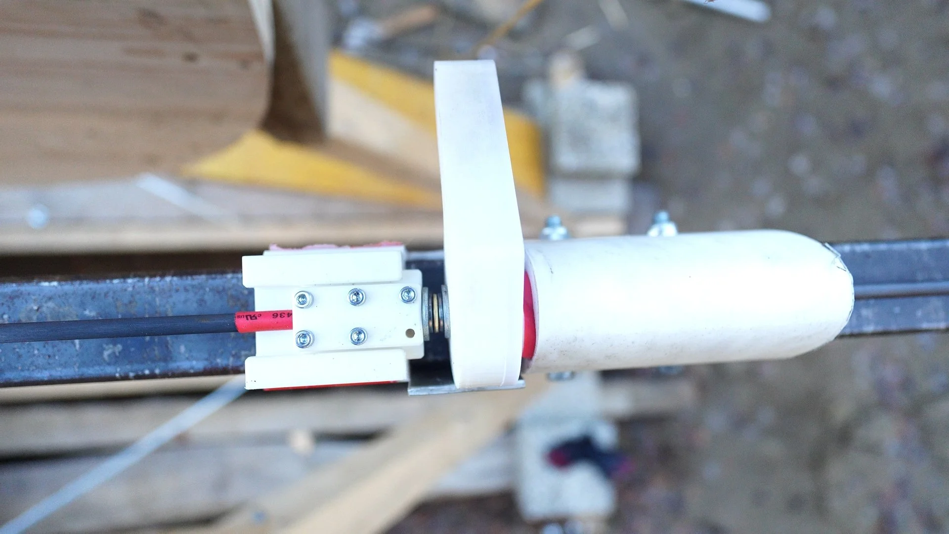
Our first focus was to find a way of reliably mounting rockets to the rotating arm. After considering several configurations, we settled on a spring-loaded gripper-like design held shut by a blocking pin. The grippers pop open under the spring force once the pin retracts. As a bonus, the conical contact points inherently supported the pivotal motion of the payload around the rear gripper as required for a flawless separation.
The first small-scale tests under load supported our choice and revealed the surprising potential of this simple design.
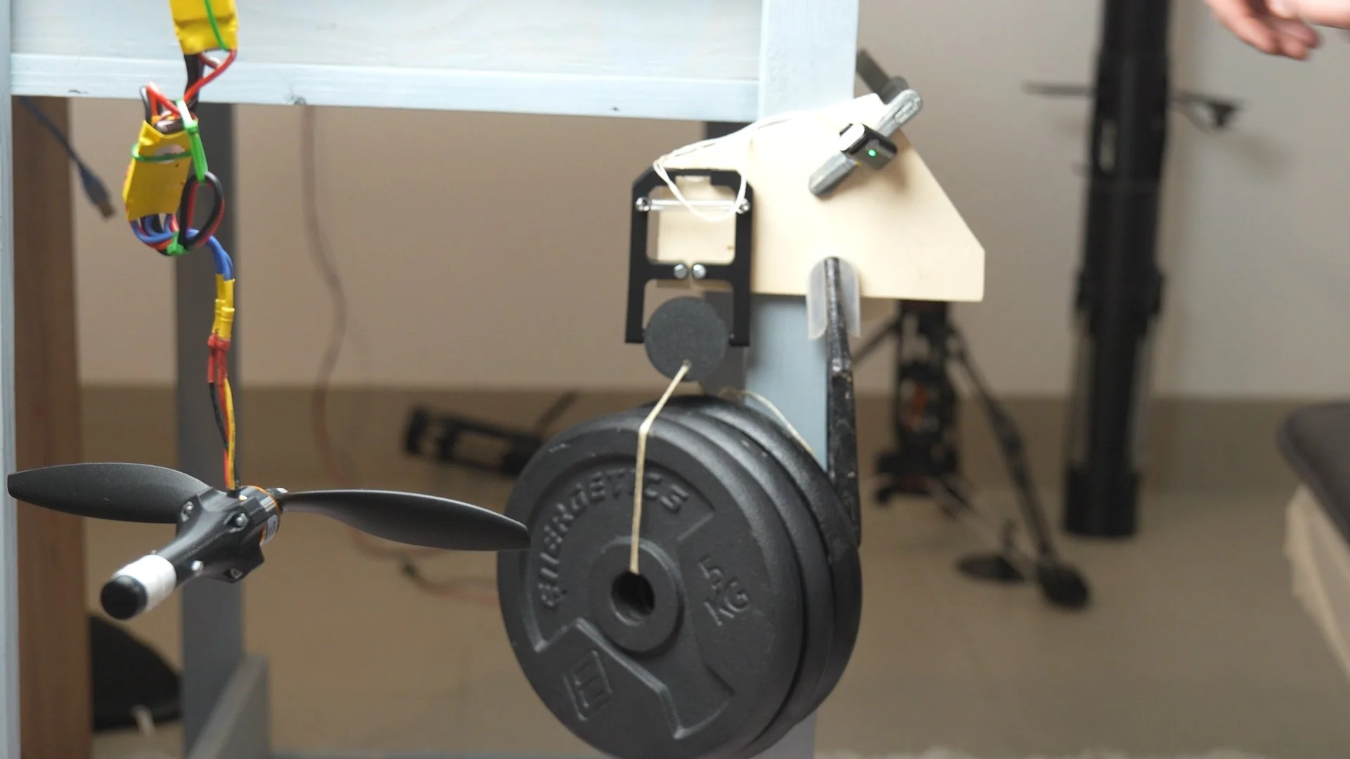
High Speed High Loading Clamp Design Initial Iteration
With the gripper concept established, the next question was how to arm and trigger the two latches. Since the front and rear differ in their function, we designed their triggers separately.
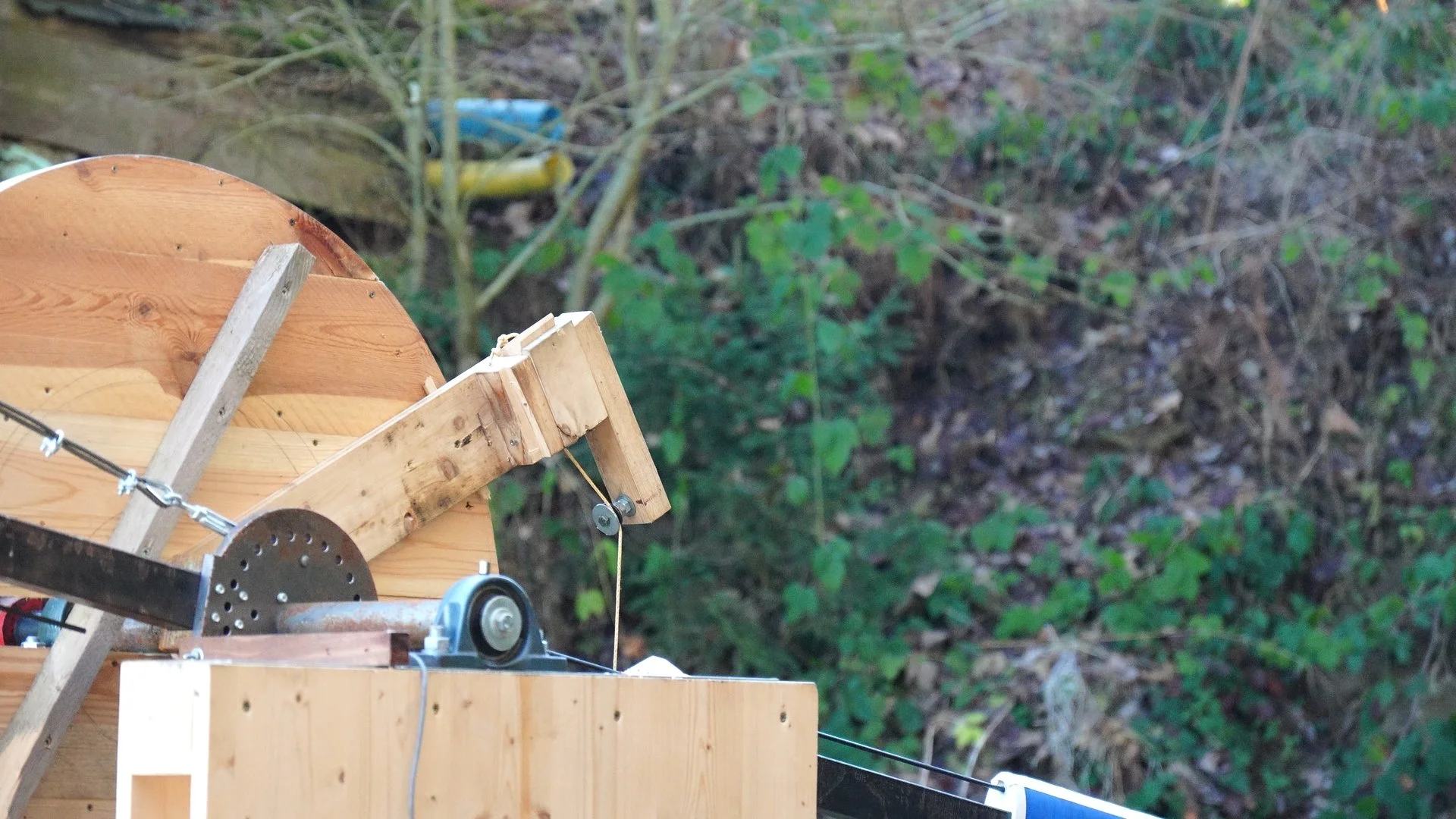
For the front release, we sought a mechanism driven directly by the system's geometry, rather than by precise timing or electronics. The solution was a ramp attached to the main structure. As the arm passes this ramp, it rotates a lever on the arm itself. A steep screw thread converts the rotation into linear motion, retracting the pin and allowing the grippers to snap open. This purely geometric trigger ensures that the release always occurs in the same manner, regardless of speed or launch conditions.
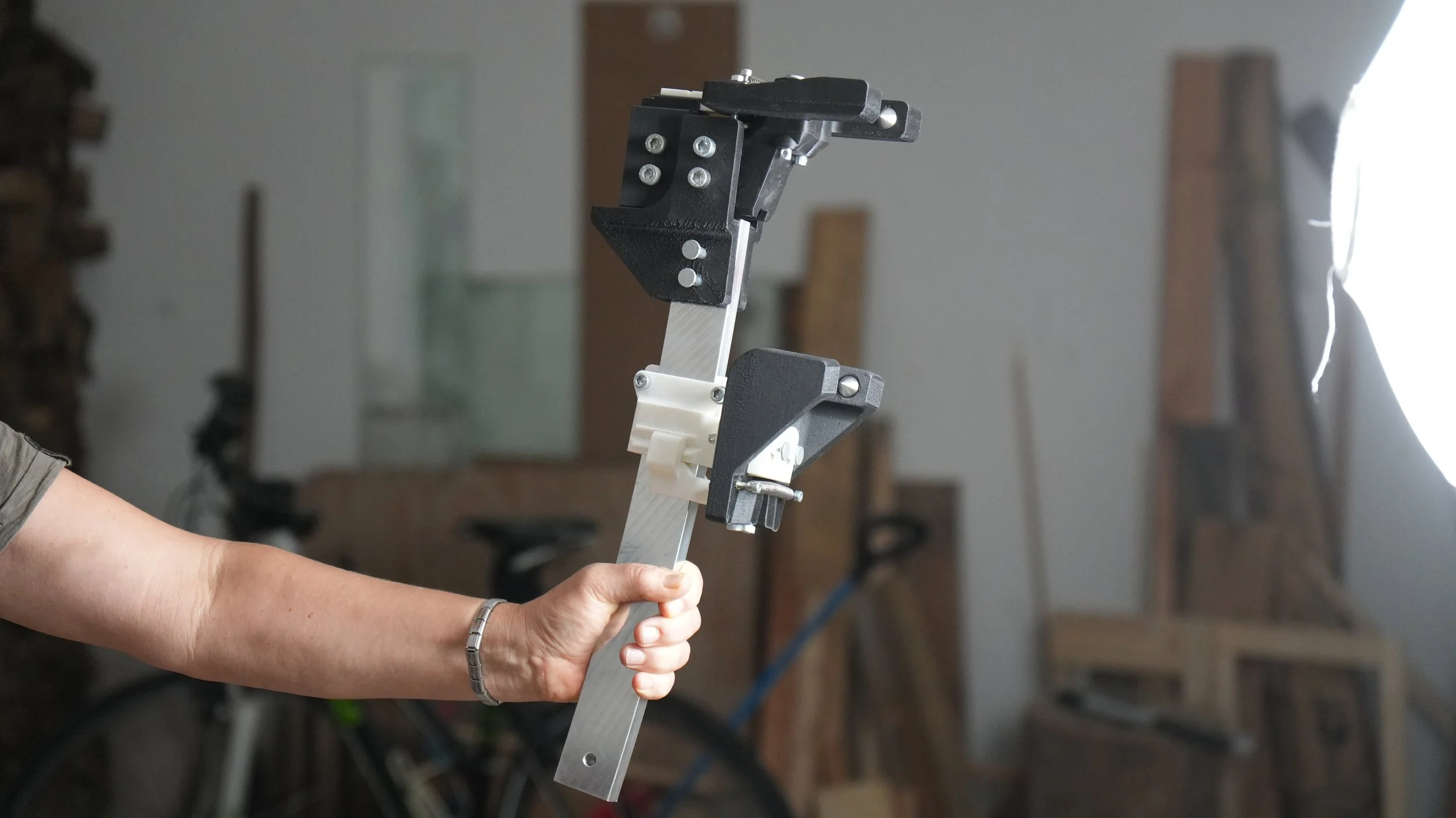
Front and rear clamp on the diameter support beam
For the rear release, we had to think of something different. To avoid sideslip, the rocket’s long axis must be exactly perpendicular to the line from the rotation center to the pivot point - in other words, at a 90° angle. So, it was natural to use an angle-based trigger for the rear, where the rocket itself would remove the blocking pin once it had rotated to this 90° angle. To adapt the system for different payloads, we introduced a scythe-like guide rail. The mounting sled can slide along this rail for coarse adjustment, while a fine screw on the blocking pin allows for fine-tuning.
We finally had a complete design for the release mechanism, but theory alone is never enough. To see whether it would hold up outside CAD, we built a small-scale prototype and put it to the test. The trials confirmed our expectations and gave us the confidence to scale up. With the promising results at hand, it was time to face the true forces of the full-scale version.
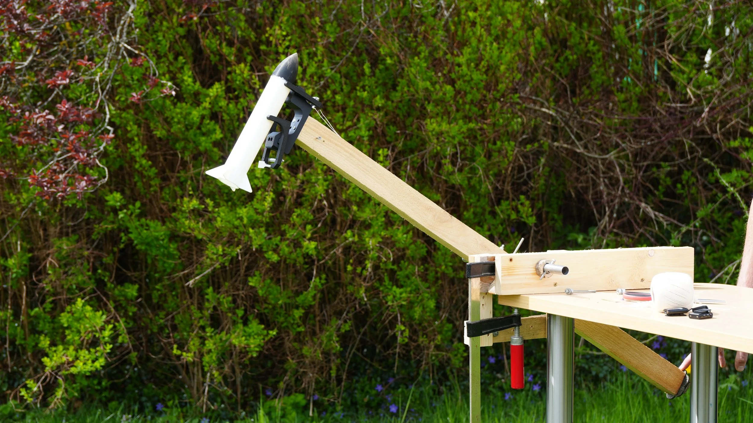
Small Scale Release Prototype
Dealing with Centrifugal Force
A frequently discussed challenge with SpinLaunch is the issue of arm imbalance following payload release. Essentially, there are two solutions for this: one option is to attach a second dummy payload of equal mass to the other end of the arm and release it into the ground simultaneously as the main payload shoots into the sky. The other option is to dimension the center bearing in a way that it can withstand the shock, possibly including a weight shifting mechanism to reduce the imbalance gradually.
For our build, we decided to use a hybrid approach, combining elements of both, where we utilize a second payload. Instead of driving it into the ground, we design the center shaft to endure a half-rotation of imbalance and then release the second payload, directly following the first one.

Two Rockets Being Launched in Rapid Progression
To address the enormous forces on the center shaft, we initially designed a custom bearing with machined and 3D-printed parts. Through a lucky twist of fate, we got hold of a set of ready-to-install bearing blocks and a massive 40 mm shaft. We decided to abandon our self-made design and use this proven, albeit slightly oversized, solution.
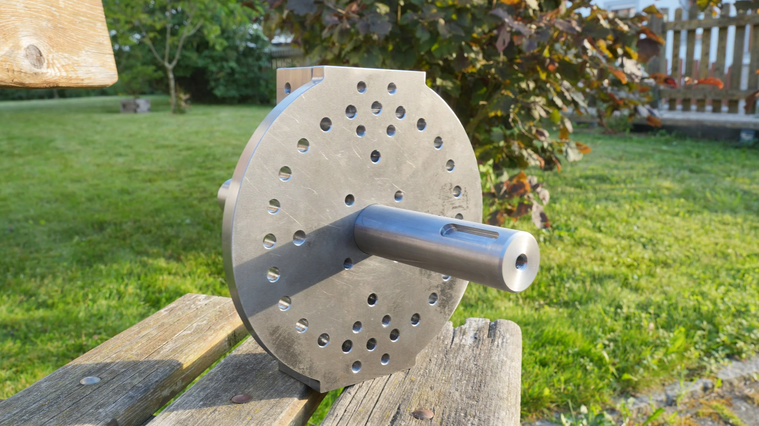
CNC Machined Parts (Shaft and Rotor Hub)
With the problem of the center bearing solved, we proceeded to the outermost part of the assembly – the release grippers – as the mass of these would also influence the design choices for the rotation arm. Due to their complexity, we utilized carbon-fiber-reinforced PPA, a 3D printing material, which, in theory, would provide a strength comparable to that of low-grade steel.
As a first approximation, we performed some rough back-of-the-envelope calculations to determine the gripper dimensions. However, since these grippers are one of the most critical components of the entire assembly, this was not precise enough. So, we performed finite element analyses, which confirmed our design. After applying some conservative safety factors and printing the parts, it was time for the first static load test.
Strength Testing of the PPA-CF Clamps
Although our test might have been subject to certain inaccuracies, it still exceeded our expectations, and we were confident to move on to the last piece of the puzzle – the main arm itself.
What makes the dimensioning of the arm slightly more challenging is the fact that its own weight has a non-negligible effect on its required cross-section because of centrifugal acceleration. Therefore, we had to resort to an iterative approach to home in on the optimal choice of material and size, minimizing cost while ensuring the necessary strength. For this purpose, we revived our Excel sheet from the initial design phase and expanded it to include all forces, moments, and resulting material stresses.
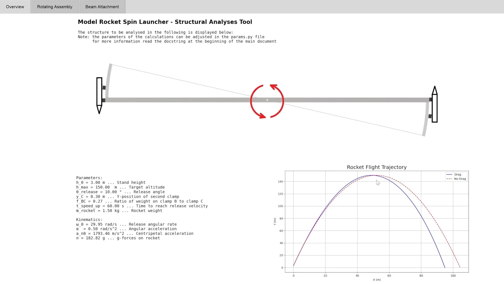
Overview Page of Structural Analyses Tool
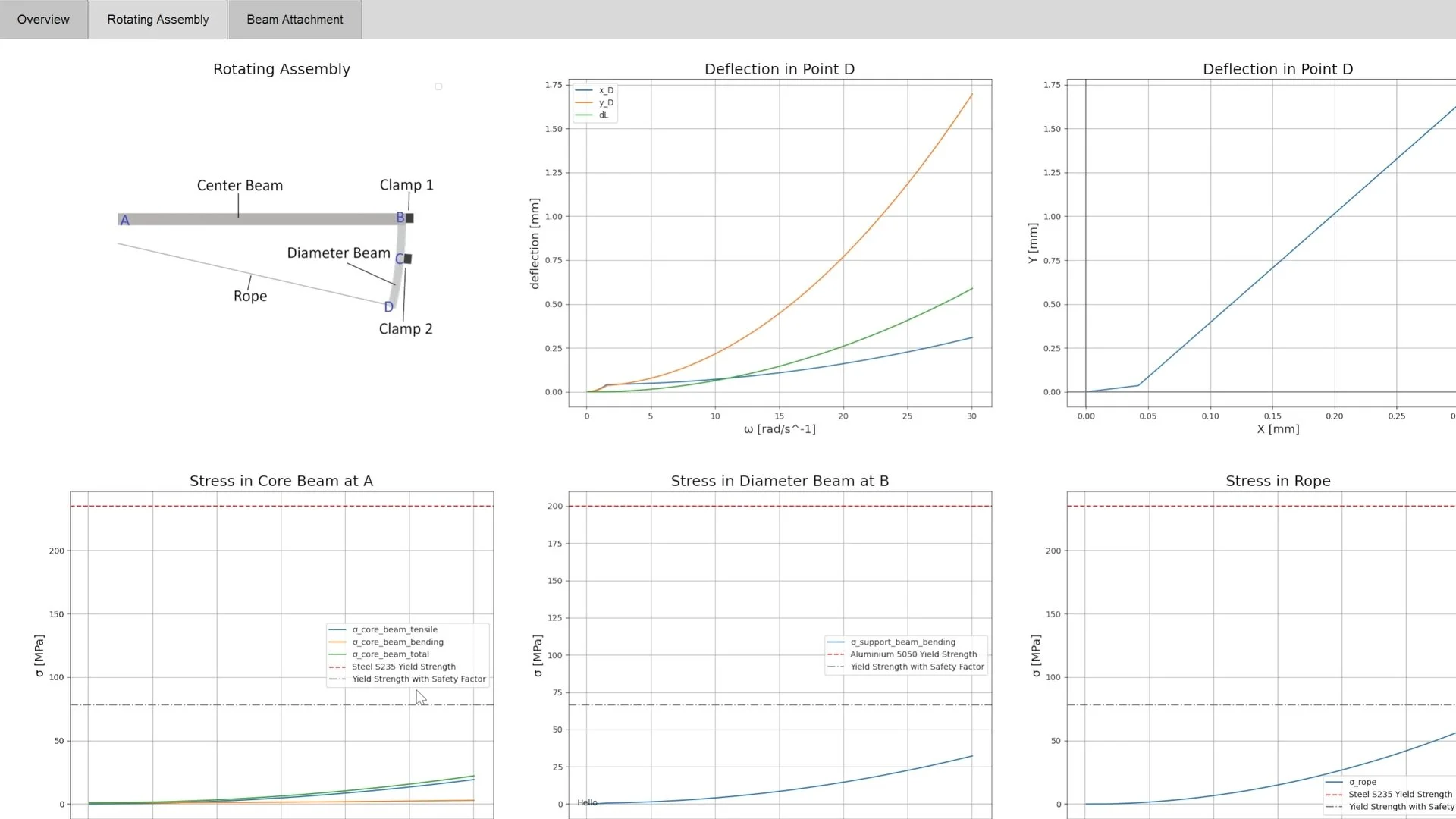
Rotating Assembly Page of Structural Analyses Tool
From Simulations to Real-World Trials
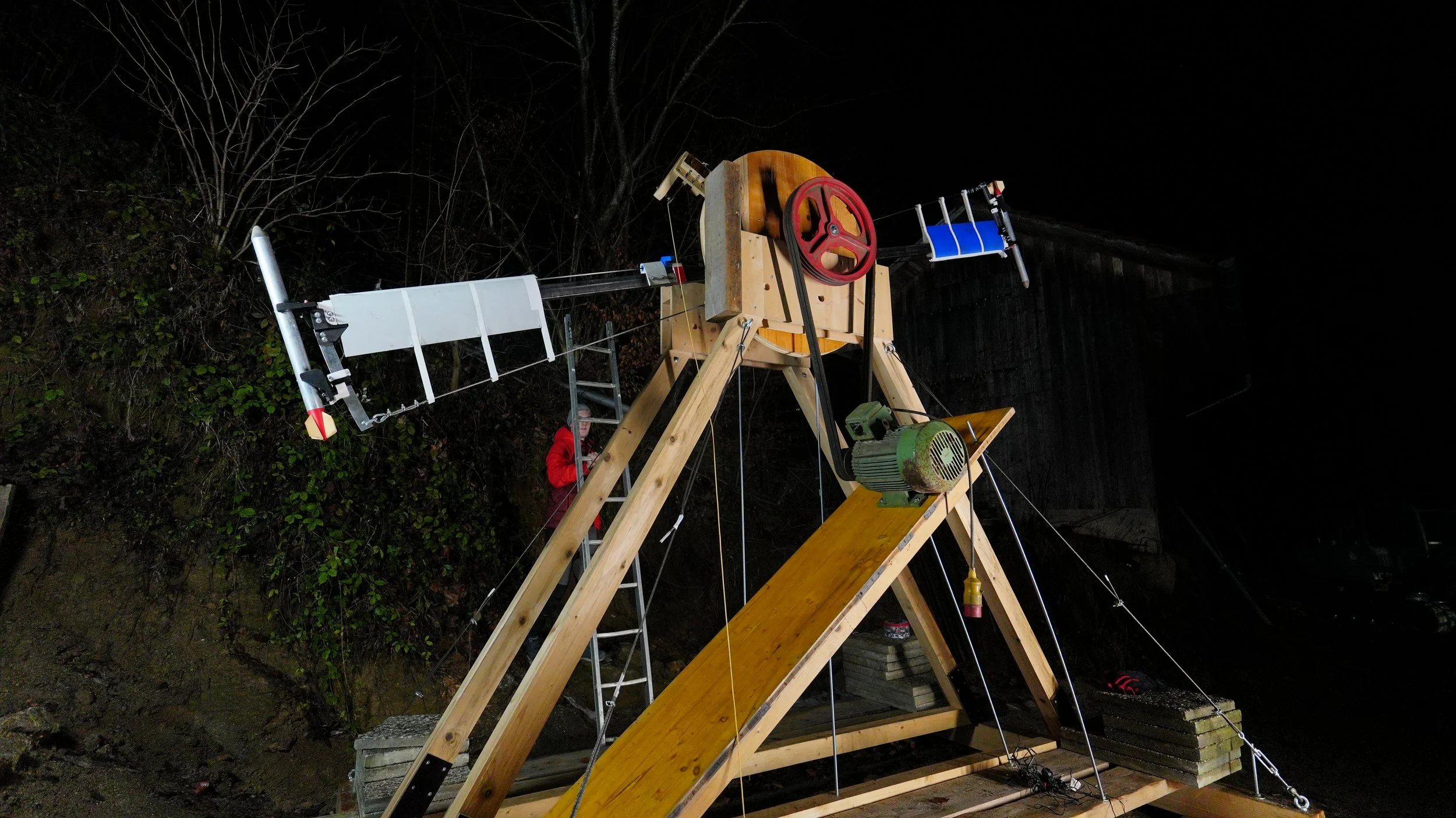
Instead of welding the support from metal profiles as originally planned, we built a more budget-friendly 2.5-meter-tall frame from square timber, stiffened with steel cables and drilled for base mounting. It wasn’t the sleek aerospace-grade structure we had envisioned, but it had a certain rustic charm - more ‘medieval catapult’ than ‘modern launch facility,’ but surprisingly functional nonetheless.
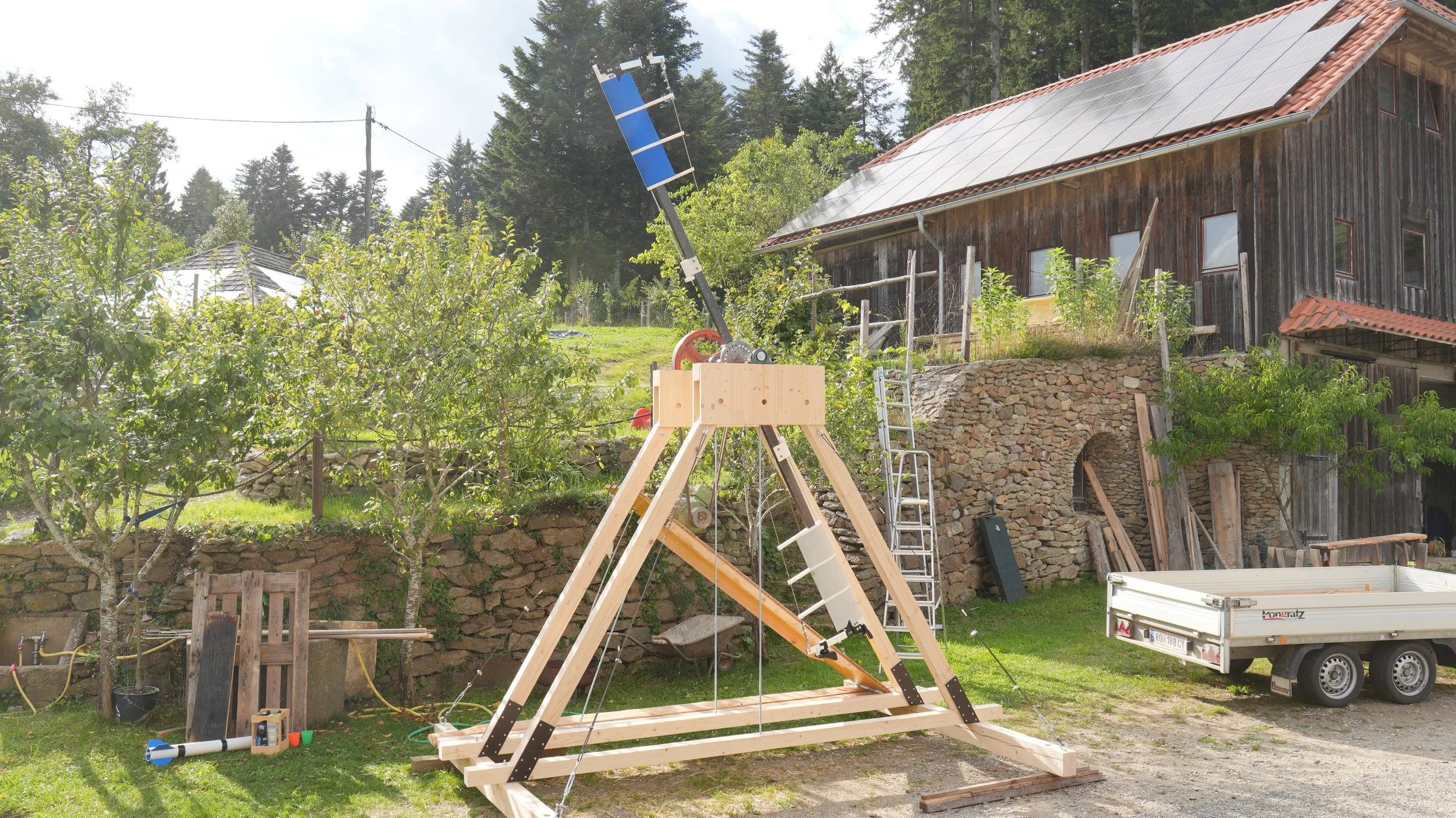
Finalized Wodden Structure with Spinning Arm Installed
Before we could bring this monster to life, a few hurdles remained: finding a motor with enough power and a suitable launch site, for example. After all, there were still some unknowns left. At full speed, we couldn’t rule out aerodynamic flutter of the arm, nor did we know how the payload’s aerodynamics would affect the release timing. We needed space - and luck was on our side. As it turned out, the neighbor from whom we got the bearing blocks had both: a 7.5 kW electric motor and an empty excavation pit, open only to one side, with nothing but fields in that direction – not the worst in terms of safety.
With all the components ready, the day of assembly had finally arrived. It would be a lie to say that everything went smoothly right away, but with some improvisation and the help of our new friend, we finished the assembly, mounted the structure on the concrete base, and prepared it for the first tests.
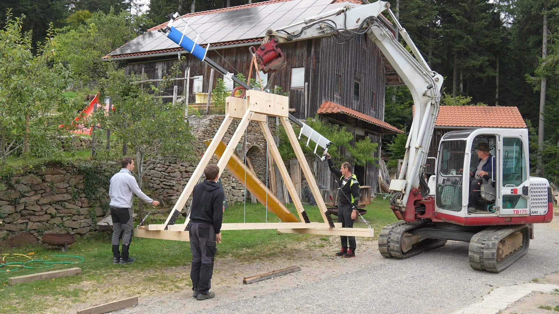
Spin Launcher being lifted into final destination
Initially, we planned to use an electric trigger system, but as we approached the end of our summer holidays, time was running out, and we opted for an improvised manual trigger to deploy the release ramp. This was not exactly elegant, but it had one major advantage: the one pulling the rope from behind a barricade had a first-class view of the launch.
Release Ramp on Release plate
The first spin tests, conducted without a payload, went well. Encouraged, we mounted our first rocket. Starting at very low RPM, the separation worked flawlessly, so we kept gradually stepping up the speed. At 200 RPM, we achieved a range of 80 meters, with still no signs of flutter. To our surprise, the release worked perfectly with hardly any tuning- something we had always hoped for but never expected. Of course, we wanted to know the launcher’s true limits. We pushed the RPM further – and that’s when things started to go off-plan.
What Went Wrong – and How We Fixed It
As we pulled the trigger at 250 RPM, nothing happened – except that the machine made a loud clacking sound. That clacking sound, as it turned out, was the launcher politely informing us that our release ramp was made of hopes and optimism rather than sufficient stiffness. High-speed footage revealed that instead of releasing the payload, the entire ramp assembly deformed, allowing the release lever to slip by.
Despite knowing that the real source of trouble was the weight of the heavy threaded rod under centrifugal acceleration, which was used to pull the release pin, we were hoping to get away with a simple fix. No sooner said than done, we reinforced the ramp mounting and turned the ramp by 180 degrees, simply accepting the rougher lever impact on the ramp.
And again, our improvisation bore fruit: we successfully surpassed the 250 RPM at which the launcher had failed previously, pushing the range to 100, 110, and, finally, to 120 meters.
At this point, we reached the limits of that design; the enormous centrifugal forces on the release rod grew beyond the material’s strength, and the inevitable happened – the 3D-printed release lever snapped in exactly the dramatic way you’d expect from a 3D-printed part that’s been bullied for too long, setting an early end to our test day.
Despite this failure, we were more than happy with the results and with what we had achieved.
Of course, we didn’t give up there. After all, we had only used 40% of the motor’s potential. The first day of testing hadn’t even ended when the team began working on the revised version of the design with two main areas of improvement: payload and release mechanism.
“The payload?”, you may ask. And indeed, our rocket was flying perfectly stable; in fact, it was flying too stably. Since our goal is to launch as far and as high as possible, we need a very aerodynamically efficient rocket. Unfortunately, the more stable the rocket, the more drag it produces due to the larger fins. So, to reach new heights, we had to trade some of the extra stability for a gain in aerodynamic efficiency.
The new design was significantly different from the previous one, featuring a heavier and more robust aluminum body, smaller fins, a tail cone, and a generally more aerodynamic shape. Overall, at maximum launch speed, this new version will fly almost three times as far as the previous version.
New Rocket Optimized for Maximum Range and Durability
The trickier part was to fix the release mechanism such that it would work reliably even at the highest launch speeds. Essentially, there were two options: make the current mechanism more robust and lightweight, or design a completely new mechanism that relies on pushing the release pin, aided by centrifugal force, rather than pulling it.
While a redesign might have been the cleanest solution, we didn’t want to take the risk of a completely new design, which we had no experience with, so we decided to go with the first approach.
Most importantly, we had to get rid of the heavy metal pull rod. The obvious choice is to use a carbon-reinforced rod. However, that brings along some problems: How can the different elements of the mechanism be connected in a way that allows it to remain adjustable? How can the rotation of the release lever be decoupled to convert the screw motion into pure translation?
Ultimately, we successfully resolved all the issues and brought everything together. Once again, we were ready for another day of testing, and we have not been disappointed.
Updated Release Mechanism Capable of Surviving Higher G-Loading
For the first test with the new setup, we went for the highest RPM the old version had successfully survived. At this point, everything could have happened – from total failure to a record launch. Luckily, the latter was the case. Our expectations have been exceeded in every way. Even though the release tuning could not have been worse – the rocket had launched sideways – we achieved a range twice as far as our previous record.
The release angle adjustment was a quick fix, and after that, we continued to step up the RPM above the old limits. After only the third launch, the rocket exceeded the bounds of our testing area, traveling over 200 meters at only 50% motor power. The math showed that this was possible, but seeing it in real life is something completely different. We could have never imagined a better conclusion to this project phase!

Single Rocket Long Range Attempt
The Road Ahead / What’s Next for Spinlaunch?
We have achieved everything we wanted, and more than we thought was even possible. But there is still so much potential left that it would be a crime to end this project here. Going forward, we will likely have to resort to other flight profiles, such as steeper launch angles or parachute deployment, to avoid overshooting the test range.
For now, we plan to add cameras and parachutes to the rocket to finally have onboard footage and reliable payload recovery. Currently, we are working on finalizing a fully remote speed-control, release, and telemetry system, which didn’t quite make it into the latest tests.
In the long term, we may also revisit more ambitious projects, such as in-flight solid stage ignition, transitioning to fixed-wing flight, or even propulsive landings.
The opportunities this base build has to offer are truly endless, and we can’t wait to embark on the next big mission.
All work shown here was conducted for educational and experimental purposes under controlled conditions. Do not attempt to replicate without appropriate facilities, training, and safety oversight.